 Skip to content
Introduction to Dieffematic: Innovation and Quality in Automation
Welcome to the world of Dieffematic, an Italian company that has been synonymous with excellence in the domestic and industrial automation sector for over 30 years. With a history rich in innovation and success, Dieffematic stands out for its ability to transform technology into practical and safe solutions for both companies and private consumers.
The History of Dieffematic
Founded over three decades ago, Dieffematic has evolved in response to the needs of a constantly changing market. A key moment in the company's history was the launch of its own e-commerce platform about ten years ago. This strategic move made automation accessible not only to technicians and industry professionals but also to private customers. Thanks to this innovation, Dieffematic has managed to open up a traditionally niche sector to a wider audience.
Product Quality and Technological Superiority
In the field of automation, quality is a decisive factor, and Dieffematic is a true pioneer in this area. Each product is the result of constant research and development, designed to ensure excellent performance even in extreme conditions. Safety, another fundamental pillar, is always at the forefront, adhering to the highest industry standards.
What truly sets Dieffematic apart from the competition is the ability to customize the solutions offered, adapting them to the specific needs of customers. It is not just about selling automation products but about building long-lasting partnerships based on trust and quality.
Services Offered
In addition to manufacturing automation products, Dieffematic offers a comprehensive range of services, including:
- Pre-Purchase Consultation: A team of qualified experts, constantly updated on new technologies, is available to assist customers in choosing the solution that best suits their needs.
- Installation: Professional support in the installation of products to ensure optimal and safe operation.
- After-Sales Support: A completely free technical and commercial support service, ready to resolve any issues or needs that may arise.
With a physical store, a production and logistics center, and an operational headquarters, Dieffematic is able to offer a 360-degree service to its customers. The company's goal is to become a point of reference for those seeking cutting-edge automation solutions, both in Italy and abroad.
In conclusion, the name Dieffematic is synonymous with innovation, quality, and customer care. A leader who, with passion and dedication, continues to push the boundaries of automation technology, making it accessible and safe for everyone.
Discover the Best Automation for Your Swing Gate
If you are considering how to improve the convenience and security of your property, exploring the various automation options for swing gates could be the perfect starting point. From linear motors to underground systems, to articulated arms, the range of products offered by Dieffematic is designed to meet every need, ensuring reliability, performance, and innovation.
Linear Motors: Power and Precision
- BH – Versatile Motorization for Every Leaf: The BH linear motor, available in 24V and 230V versions, is designed for swing gates up to 3 meters. Perfect for residential and commercial installations, the BH offers versatility thanks to the various available stroke lengths: 500mm, 400mm, and 300mm. For more information, visit our BH Kit.
- BHE – Vertical Robustness: If you are looking for a piston rod motor, the BHE is an ideal solution. With its vertical motor relative to the piston and direct release with a triangular key, it is suitable for moving gates from 2.50 m to 3.50 m. Again, the 24V and 230V versions ensure flexibility and adaptability. Learn more about the BHE Kit.
- VH – Compact Efficiency: The VH linear motor, with a double stroke size (400 and 500mm), supports gates up to 3.50 m. It is an economical but powerful solution, perfect for those seeking value without compromising on quality. Visit the VH motor page for more details.
- PM – Quietness and Flexibility: The PM motor, available in 300, 400, and 600mm sizes, is the ideal choice for those looking for quiet swing gate automation. Perfect for residential use, it can motorize gates up to 3.50 m. Discover the PM Kit.
Articulated Motors: Supreme Adaptability
For situations requiring greater robustness, articulated motors like ARTILUX PLUS and ARTILUX OLD offer perfect solutions. The ARTILUX PLUS is suitable for gates up to 2.50 meters, while the more robust ARTILUX OLD can automate gates up to 3.50 meters. Both are available in 230V versions, with the ARTILUX OLD in both 230V and 24V versions.
Underground Motors: Elegance and Discretion
If you are looking for invisible automation, the Cromo underground motor is the ideal choice. Available in dual 24V and 230V versions and supplied with plastic, stainless steel, or galvanized iron cases, the Cromo can move gates up to 3 meters and 300 kg in weight.
Technical Considerations for the Right Choice
The choice of the right automation for your swing gate depends on several key parameters:
- Gate Weight: Essential to determine the necessary motor power.
- Gate Type: Panelled or open, as wind load affects performance.
- Pillar and Hinge Structure: Crucial for the installation and choice between piston and articulated arm.
Dieffematic Automation Kit PM1 Corsa 300 230v Irreversible
Achieve maximum efficiency and reliability with the Dieffematic PM1 Corsa 300 230v Irreversible Automation Kit. This kit is the ideal choice for automating your two-leaf swing gate, ensuring high performance and durability over time.
Main Features
- Linear Electromechanical Actuator: Designed for residential use, the actuator is built entirely of metal with a stainless steel rod, ensuring robustness and long lifespan. The structure is designed to last over time without constant maintenance.
- Extended Compatibility: Ideal for gates up to 3.00 meters in length and a maximum weight of 250 kg. This allows adaptation to different gate sizes, offering flexibility and versatility in installation.
- High-Performance Motor: The electric motor can deliver high performance with a power of 200 W and adjustable thrust from 500 to 3000 N, ensuring smooth and powerful movement of the gate leaves.
- Secure Lock and Easy Release: The actuator maintains the lock in both closing and opening without the need for an electric lock. The convenient release with key, located on the motor unit, allows quick intervention in case of emergency.
Specific User Benefits
- Ease of Installation: The kit does not require modifications to the existing gate, making installation simple and quick. This allows you to automate your gate without complications and with minimal effort.
- Low Maintenance: Thanks to its robust construction and high-quality materials, the automation requires little maintenance, offering you a practical and durable solution.
- Safety and Control: The control unit with built-in receiver offers various operating logics, surge protections, and obstacle detection, ensuring safe and reliable gate operation.
- Versatility and Adaptability: Suitable for both symmetrical and asymmetrical gates, the kit allows independent adjustment of the gate leaves, ensuring optimal operation in any situation.
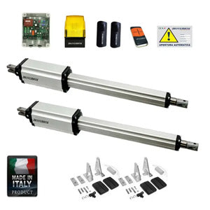
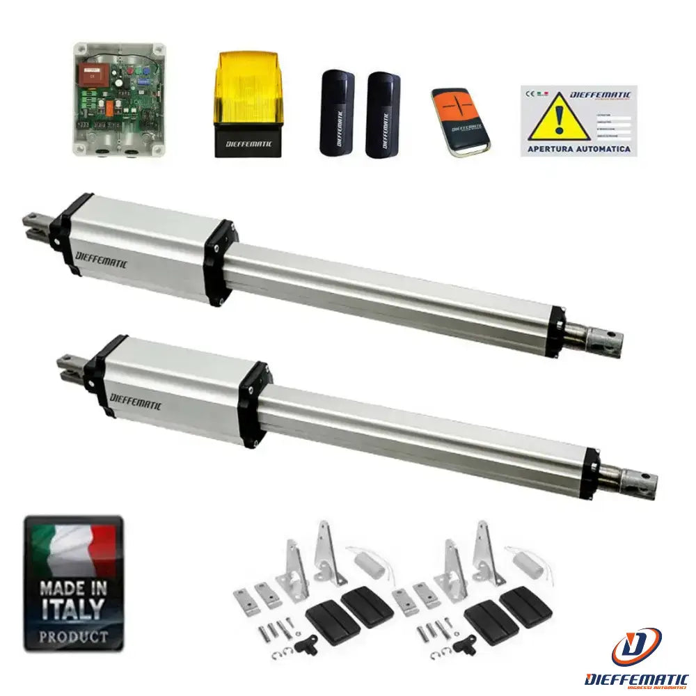
Kit Composition
- 2 Electromechanical Operators for Swing Gates: Designed for leaves up to 3 meters in length and 250 kg in weight. They do not require an electric lock and offer a maximum opening angle of 120°.
- Control Unit: Waterproof box with trimmers for motor force adjustment, obstacle detector, slowdown in opening and closing, and 4 operating logics. Includes inputs for photocells, safety edges, and electric lock management.
- Single-Channel Radio Receiver: Integrated into the control unit, operating at 433.9 MHz with a range of 20 meters.
- 4-Channel Rolling Code Remote Control: For secure and personalized control.
- Pair of Wall-Mounted Photocells: To ensure maximum safety during gate operation.
- 230v Flashing Light: For visual alerts during gate movement.
- Installation Accessories: Everything needed for easy and quick assembly.
- Instruction Manuals: Detailed and in Italian, for mechanical and electronic installation.
Learn More
The Dieffematic PM1 Corsa 300 230v Irreversible Automation Kit is the perfect solution for those seeking reliable and high-quality automation for their gate. Click on the links for instruction manuals and discover how this kit can transform your gate into a state-of-the-art automated system.
How to Install Swing Gate Automation: PM and PM1 Model
Correct mechanical installation of linear pistons is essential to ensure the functionality and longevity of automation systems. This tutorial provides a detailed guide on the necessary steps for installing our linear piston models, including PM, PM1, BHE, BH, VH, and PH motors. Carefully following each step ensures a safe and efficient installation, avoiding malfunctions and future problems.
General Overview of Mechanical Installation
Mechanical installation of linear pistons requires precision and attention to detail. Here is an overview of the main phases involved in the process:
- Preparation and Collection of Necessary Tools
- List of required tools
- Workspace verification
- Measurement Calculations
- Measurement of A and B dimensions
- Determination of the required piston stroke
- Piston Mounting
- Initial positioning of the piston
- Fixing the bracket and gate
- Post-Installation Verification
- Gate movement test
- Final adjustments
Preparation and Collection of Tools
Before starting, make sure you have all the necessary tools and materials for the installation. Here is a list of what you might need:
- Measuring tape
- Bubble level
- Electric drill
- Appropriate screws and bolts
- Piston support
Measurement Calculations
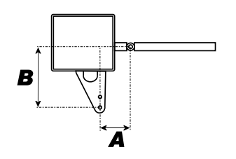
Identifying A and B Measurements
Correct installation depends on two main measurements: A and B. These measurements represent the projections from the gate hinge.
- Measurement A: Distance from the gate hinge to the pillar.
- Measurement B: Distance from the gate hinge to the piston's mounting position.
These measurements, added together, will be used to determine the required piston stroke.
Choosing the Piston Stroke
The appropriate choice of piston stroke is crucial. Here is a practical example:
If A is 20 cm and B is 20 cm, the total sum is 40 cm, so the piston stroke must be at least 40 cm to ensure a complete gate opening at 90 degrees.
In particular situations where the hinge is further or closer, these measurements may vary, making it essential to find the right balance between gate length and piston stroke capacity.
Piston Mounting
Initial Piston Positioning
It is crucial to start with the correct positioning of the piston relative to the pillar and gate:
- Position the piston so that it aligns with measurement A from the gate hinge.
- Fix the bracket to the pillar, ensuring it is firmly and correctly positioned.
Bracket and Gate Fixing
Once the piston is positioned, follow these steps:
- Attach the piston to the bracket using sturdy bolts.
- Ensure that the piston is correctly aligned with the gate.
- Check that all connections are tight and secure.
Post-Installation Verification
Gate Movement Test
After completing the installation, it is important to test the system to ensure it works correctly:
- Slowly open and close the gate to check for any resistance or unusual friction.
- Ensure that the piston completes the movement without any issues.
Final Adjustments
If you notice any issues during the test, some adjustments may be necessary:
- Check A and B measurements again to ensure they are correct.
- Adjust the piston's position or bracket connections if necessary.
Conclusion
Carefully following these steps ensures correct and efficient installation of linear pistons on gates. A proper installation not only guarantees smooth operation but also prolongs the lifespan of the automation system. For more technical details, consult the mechanical installation manual.
Mechanical installation is a process that requires precision and attention, but with the right preparation and correct instructions, professional and reliable results can be achieved.
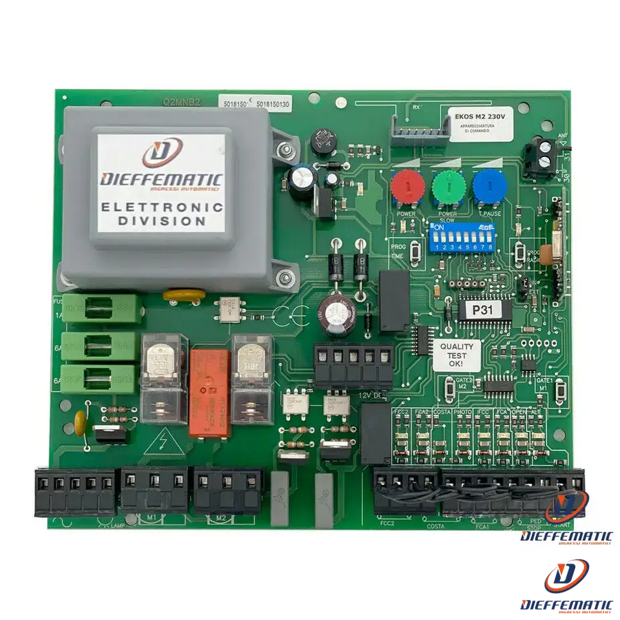
EKOS 230 M2 Electronic Control Unit Installation: Complete Guide
Introduction
Welcome to the complete guide for installing the EKOS 230 M2 electronic control unit, designed for managing two-leaf swing gates or double sliding gates. Correct installation and programming of this control unit are essential to ensure efficient and safe operation of your automation system. In this guide, we will explore every aspect of the installation in a detailed and clear manner, ensuring that you can easily follow each step.
General Installation Overview
The EKOS 230 M2 control unit is designed to make gate automation simple and reliable. Here is an overview of the main steps for installation:
- Preparation of Necessary Materials and Tools
- Electrical Connections of the Control Unit
- Connecting Motors and Accessories
- Configuring DIP Switches
- System Programming and Testing
1. Preparation of Necessary Materials and Tools
Before starting the installation, make sure you have all the necessary tools and materials. Here is a list of what you will need:
- EKOS 230 M2 control unit
- Screwdrivers (cross and flat)
- Pliers
- Electric tester
- Electrical cables and connectors
- Gate motors
- Photocells
- Flashing light
- Capacitor
2. Electrical Connections of the Control Unit
Let's start with the electrical connections of the control unit. This phase is crucial for the correct functioning of the system. Follow the steps carefully:
Main Connections
- 220V Input: Connect the power cables to contacts 1 and 2.
- Flashing Light: Connect it to contacts 3 and 4.
- Courtesy Lights: Connect them to contacts 3 and 5. Note that the courtesy lights turn on for 180 seconds from the moment the start contact is received.
Motor Connections
- Motor 1:
Connectors 6-7: Connect the motor phases with the capacitor in parallel.
Connector 8: Connect the motor common.
- Motor 2:
Connectors 9-10: Connect the motor phases with the capacitor in parallel.
Connector 11: Connect the motor common.
3. Connecting Motors and Accessories
Proceed with the connections for managing photocells, limit switches, and other safety features:
Photocells and Safety
- Opening Photocell: Connect the contacts to terminal 15-17.
- Closing Photocell: Connect the contacts to terminal 16-17.
- Limit switch for motor 1: Connections for common, close, and open.
- Limit switch for motor 2: Connections for common, close, and open similar to those of motor 1.
- Stop contact: If not used, it should be bridged.
Pedestrian and Start Commands
- Pedestrian entrance: NA contact connected to terminal 22.
- Common contact: Terminal 23.
- Start input: Terminal 24. These contacts are normally open and should be left open if not used.
4. Configuring DIP Switches
The DIP switches allow configuring various aspects of the control unit's operation.
Dip Switch Configuration
- DIP 1: Enable/disable automatic closing.
- DIP 2: Manage condominium or step-by-step mode.
- DIP 3: Access radio memory for some commands.
- DIP 4: Enable the ram blow for the electric lock.
- DIP 5: Manage photocell safety.
- DIP 6: Configure the flashing light.
- DIP 7: Enable/disable slowdown.
- DIP 8: Set the management for hydraulic or electromechanical motors.
5. System Programming and Testing
Once all connections are made, it is time to program the control unit:
- Setting the potentiometers:
- Power: Manages the force during normal operation.
- Power Slow: Manages the force during the slowdown phase.
- T-Pause: Sets the pause time, between 5 and 120 seconds.
Remote Control Programming
- Total opening: Press the Prog Radio button once.
- Pedestrian opening: Press the Prog Radio button twice.
System Test
Follow these steps to test the correct programming:
- Prog Time: Press the button for two seconds. The LED remains on, indicating that programming is in progress.
- Gate movement: Press Gate 1 for motor 1 and Gate 2 for motor 2, following the opening and closing sequence with slowdown.
Conclusion
Correct installation and programming of the EKOS 230 M2 control unit are essential to ensure effective and safe operation of your gate automation system. For more details or insights, consult the complete installation manual at installation manual.
FAQ on Swing Gate Automation
1. Who certifies the automatic gate?
The certification of the automatic gate is a crucial aspect to ensure the safety and quality of the installation. - Final Installer Certification: The final installer is responsible for issuing the certification of the automatic gate. This guarantee includes both electronic and mechanical components. - UNI EN ISO 9001 Certified Product: Our automatic gate complies with UNI EN ISO 9001 standards, ensuring high levels of quality and safety. - Safety Assurance: The safety of the installation is guaranteed by the electrician or qualified installer, who ensures the product's safety.
2. Why does the automatic gate open but not close?
This issue is commonly caused by problems related to safety devices such as photocells:
- Photocell Issue: A malfunction in the photocells can prevent the gate from closing while the opening will work correctly.
- Security in Connections: Security can be enabled in the control unit connections to allow opening, but a faulty photocell could block closing.
- Solution: Check the photocells, clean them regularly, and verify the connections on the control unit.
3. Why does the gate open and close by itself?
This abnormal behavior is often the result of radio interference:
- Radio Interference: During the memorization of remote controls, external radio signals can interfere with the control unit, causing involuntary manipulations.
- Radio Memory Reset: The quickest solution involves resetting the radio memory and re-memorizing the remote controls to eliminate unwanted signals.
4. Why does the gate open only from close range?
The limited range of the remote control or radio interference can reduce the system's effectiveness:
- Remote Control Range: It may be due to a reduced range of the remote control or antenna.
- Radio Interference: Updates in surrounding radio frequencies can affect regular operation.
- Solutions:
- External Antenna or Amplification: Increase the range by installing an external antenna or amplifying the existing one.
- Shielded External Receiver: In installations with many interferences, a shielded external receiver can ensure a clean radio channel and improve the remote control's range.
